Background
The X45e function units can be used in more generic applications outside the X45e platform. This article focuses on the speed mode. It exists in two different sub modes, Sensor mode or Limit switch mode. They are implemented exactly the same way for conveyor drives.
For deeper information please check the following manuals:
- User documentation – Electrical System (X45e)
- User documentation – Parameter Setting Tool
Prerequisites
Hardware
- PC (Windows 7 or later)
- X45e function unit (with power cables)
- Parameter Setting Tool cable (X45e) or mini USB cable depending on hardware version
Software
- X45e – Parameter Setting Tool
Software version
Make sure the unit has the latest software versions installed. Look at MyFlexLink under the Download Area for information about the latest release. This article was written when the FEG version 59 was the latest version. The PST version used is 3.0.12.
Wizard
To set the proper parameter setting to the function unit the wizard is a good help. This is started with the command Change Node.
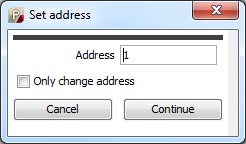
The first step of the wizard is the setting of the address of the node. This node address can be set to any required value (max 126). If the unit should be a part of a system with one configuration file it has to have a unique address even though it is not connected to a field bus.

The next window in the wizard decides which standard (physical) type the unit should be set to if it is a part of the X45e platform. But there is also two generic control options, Position mode and Speed mode. The Speed mode option should be selected in this case.

The Network settings window should in the stand-alone case be set to None. If an external network is to be used this is specified here. CANopen, DeviceNet, Ethernet/IP or Profinet are possible options.

The last popup window in the wizard is the control settings window. The first two choices (Enable-Reset and Control) could not be set to anything else than Autonomous if no network was selected in the previous window. If a network is chosen Line control is the only possible alternative.
The Variant parameter could be set in two different modes, Sensor or Limit switch mode. Both these variants has two speed setpoints but they differ in how they are used.
The Sensor mode is basically controlling the speed setpoint with one digital input (DI3). If this digital input is activated the speed setpoint 2 is used as the speed on the conveyor. If DI3 isn’t activated the speed setpoint 1 is used.
The Limit switch mode is controlling the speed setpoint by using two digital inputs (DI3 and DI4). The conveyor is running with speed setpoint 1 until DI3 is activated. Then the conveyor is stopped a number of milliseconds. This time delay is specified in the parameter Limit switch wait. After this delay the conveyor is started again but this time with the speed setpoint 2. It is running with this speed until DI4 is activated. Then the conveyor is stopped once again in the same delay time as described above. Then the conveyor is starting again with speed setpoint 1 and the sequence is repeated all over again.
The Interlock parameter controls (by the status of digital input DI4) if the unit should be temporary stopped even though the enable signal is set. In stand-alone mode the enable bit is always on so the Interlock signal is the only way to stop the drive. If this parameter is set to None the interlock function is not active. If it is set to Normally open then DI4 must be unactivated in order to get the conveyor to run. On the contrary Normally closed means DI4 has to be activated to run the conveyor.

After the wizard is completed the unit is updated with these settings (if working in Direct mode). Also all of the parameters in the settings windows are updated to the unit. If some of these parameters should be changed this could be done via the Parameter Setting Tool.
There is also a possibility to adjust the speeds setpoints using the digital input signals. The digital input 1 (DI1) is increasing the speed setpoint parameter. It increases the values with 1 rpm/s the first two seconds. After this it increases the value with 10 rpm/s. The digital input 2 (DI2) is decreasing the speed setpoint parameter with the same timer function. This fine tuning procedure is adjusting the speed setpoint that currently is chosen.