This article is not on how to design a guide rail symbol, it's on how FlexCAD AutoCAD works with guide rail symbols.
A Guide Rail Symbol is used to facilitate calculation of how much guide rail and how many guide rail bracket parts needed on a conveyor. The user can of course put out the guide rail brackets needed physically along the conveyor but in larger layouts this is a tedious work and the need of guide rail is cumbersome to calculate. Also the Guide Rail Symbol can take care of fasteners needed.
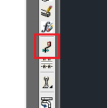
The first thing to do is to design what will be the guide rail symbol and the design is done in the drawing, there is no need to start a new drawing, using FlexCAD parts. Non-FlexCAD parts can also be part of the user symbol but will not show up in the part list. When the design is done, the next step is to create the guide rail symbol. That is done by clicking the Guide Rail Symbols icon, see picture below.
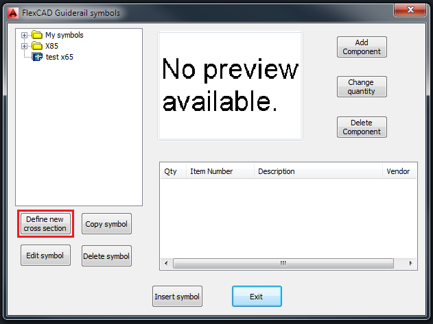
Now the FlexCAD Guiderail Symbols window opens. In that window, click the Define new cross section button.
Clicking this button opens up a new dialog window, in which the user can build a folder structure to more easily find and maintain user symbols.
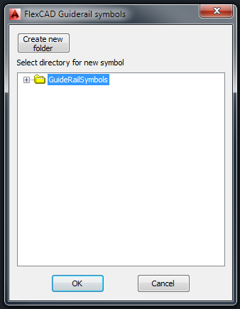
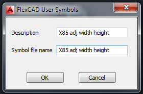
After creating a new folder or choosing an existing folder where to put the guide rail symbol, the user is asked to select what objects to be included in the guide rail symbol, and after pressing Enter, the user is asked to point out an insertion point, this will be the insertion point of the guide rail symbol block when the guide rail symbols is entered into a drawing. A new dialog window opens where the user is asked to enter a description of the guide rail symbol and a file name of the guide rail symbol. Enter a fitting description and then by clicking in the Symbol file name text field, what is written in the Description field is entered there as well. What it says in the Symbol file name text field will be the name of the .dwg file.
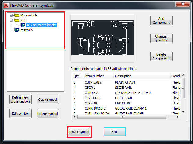
The objects that were chosen to be part of the guide rail symbol are removed from the drawing and the function window is closed. To insert the symbol into the drawing, start the function again. The FlexCAD Guiderail symbols window opens and in the top left part of the window, look up the symbol and then click Insert, see picture below. The FlexCAD Guiderail symbols window closes and the symbol is at the cursor and it can be placed where ever the user wishes.
Adding fasteners to a guide rail symbol as well as editing and copying a guide rail symbol are done in the same way as for user symbols, please see those articles regarding these matters.