Background
The units in the X45e platform can be controlled in three ways. Either you have no communication with the units besides the four digital inputs. This is referred to as autonomous or stand-alone mode. If more communication is required there are two options, DeviceNet or CANopen. They are both versions of the CAN protocol. This article focuses on how to work with the CANopen alternative.
In the following case we have a Siemens PLC (S7-300) and a Systeme Helmholz CANopen Master (CAN 300 PRO). This solution requires access to the standard PLC blocks provided by Systeme Helmholz. The description is focusing on giving an overall view of the topic.
For deeper information please check the following manuals:
- User documentation – Electrical System (X45e)
- User documentation – Parameter Setting Tool
- Manual for the CAN 300 PRO module
Prerequisites
Hardware
- PC (Windows 7 or later)
- Siemens PLC (S7-300)
- CAN 300 PRO communication module
- USB cable for connecting to the CAN module
- X45e units (with power cables)
- Parameter Setting Tool cable (X45e)
- CAN cables (resistor, cable with open end, daisy chain cable, bus termination)
Software
- Siemens Step 7 or TIA
- X45e – Parameter Setting Tool
- CanParam (Systeme Helmholz)
- Communication handling blocks (Systeme Helmholz)
What to do
X45e
- Make sure the nodes are supplied with power properly.
- Connect a PC via the Kvaser cable to the B-Bus connector on the node.
- Launch Parameter Setting Tool and set the Network > X45e > B-Bus (CANopen)
- Network > Scan network F12 to see the nodes on the network
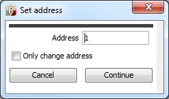
- Use the command Change node set the correct setting for each node
- The first thing to set is the node address.
Then the function type of the unit has to be specified. The possible alternatives differs depending on if it is a conveyor motor or a function motor.

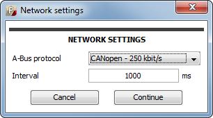
Next window is for setting all network parameters
A-Bus protocol has to be set to CANopen – 250 kbit/s.
The Interval is the cycle time for the PDO communication. For a drive unit it might be good enough to keep the default value (1000 ms). For function units (e.g. diverters) this value can be lower to 50-100 ms.
- In the last window in the X45e setting the Enable – Reset should be set to Line control. This means the X45e unit is waiting for these two command bits for enable and reset.

Physical network
- Make sure the CAN 300 PRO communication module is mounted correct including a termination resistor.
- The first CAN cable should be open in one end. In this end connect CAN H,L and GND to a D-sub connector and connect this to the module. The other two parts is the power supply for the bus. These must be connected in this end to a 24VDC power supply.
- Continue to link all motor using daisy chain.
- The last motor should have an M12 CAN bus termination in the end.

CAN 300 PRO
The CAN 300 PRO module must be configured with the CanParam software.
- The master settings Node ID must be equal to the settings done on the DIP switches on the module.
- Baudrate must be 250K.
- The size of the PLC I/O buffer should be enough to contain all slave info
- The RPDO communication must be specified for each slave
It should be set to 2 Bytes (2 * Unsigned8)
The communication type must be set to change on PLC cycle
- The TPDO should be set to 5 Bytes (5 * Unsigned8)
PLC
- Use the FB20 from Systeme Helmholz to read IO. This is the TPDO that sends information from the X45e units to the PLC .

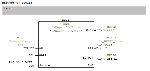
- Use the FB21 Systeme Helmholz to write IO. This is the RPDO that sends information from the X45e units to the PLC .
- The FB24 is used both for reading and writing parameters to the X45e units. The SDO_Request parameter controls if the SDO should be read or write. The SDO_Index and SDO_Subindex controls which parameter (setting) that will be in focus.
It is very important that this SDO-function block called in sequence if more instances are used.
Check in the SDO table in the User Documentation – Electrical System for more detailed information. (note that Index is in hex and Subindex in dec)

Trouble shooting
If the communication is not working as expected there are a number of different things to check and tools to use.
- CanParam
The first thing is to check the status of the CANopen network through the CanParam software. Here all slave nodes should appear and be in operational mode.
- PST (X45e)
The status of the nodes could also be checked from the PST software (Monitor page). Here it is possible to see exactly which bits that are received from the PLC and also the status of the feedback.