Working with Controls require the Controls tab in the ribbon to be selected.
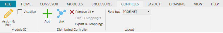
When modules and drive units are configured, distributed controllers can be linked to the modules.
Step 1: Assign Module ID
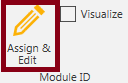
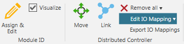
Click Controls tab -> Module ID group -> Assign & Edit button and a Assign & Edit Module ID panel is shown on right hand side.
Tip! the location of the panel can be adjusted to your liking by clicking and selecting the panel and then move it with the mouse. A docking panel shows how the panel can be placed in various positions.

When the radio button Assign to selected conveyor is active module ID numbering is automatically assigned for a selected conveyor. The base for numbering and the increment can be changed prior to selection. It is possible to edit any module by changing mode to Edit selected component.
Tip! the module ID can be visualized after assignment by using the checkbox Visualize in the Module ID group.
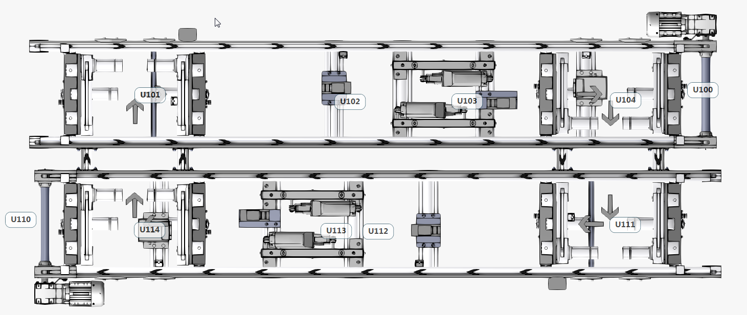 Example of layout with assigned module IDs
Step 2 Add Distributed Controller
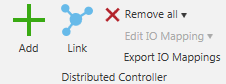 Click Controls tab -> Distributed Controller group -> Add button and a distributed controller is loaded into the 3D world. It can be placed on compatible beams and on the floor by clicking on its requested location. Exit the command by pressing Esc.
 Example placement of a Distributed Controller
Tip! The position of the Distributed Controller can be modified at any time by selecting the Distributed Controller and press the Move button in the Distributed Controller group.
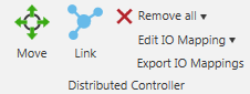
Step 3 Link Controller and Modules
Click Controls tab -> Distributed Controller group -> Link button and a SCDC Placement panel is shown on right hand side.

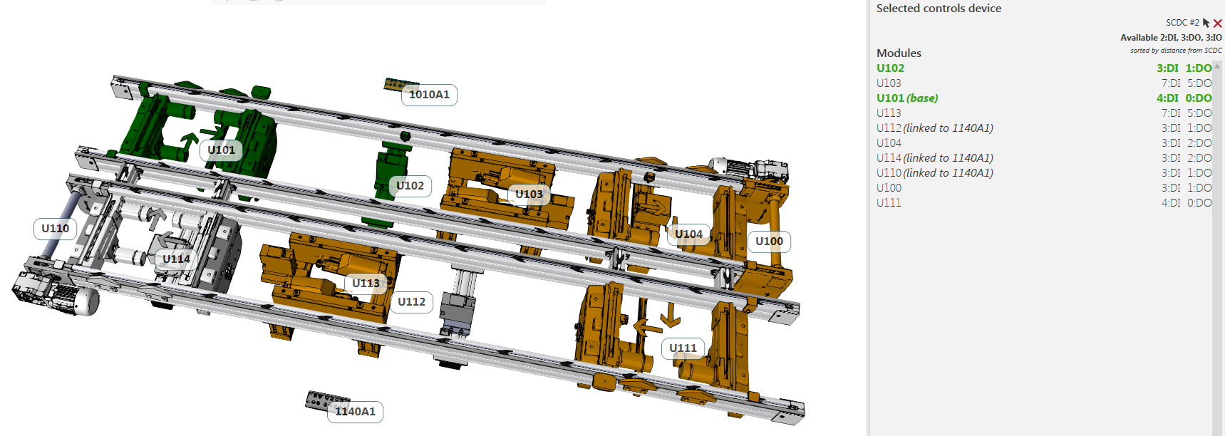
Linking is done for one controller at the time. Select one controller and assign modules. The first chosen module will be assigned as base module. A base modules IO mapping will correspond one to one with its electrical drawing. Additional assigned modules will then be linked as peripheral modules. In practice this means that the IO assignment will be dependent on available connectors on the distributed controller.
Tip! Base and peripheral module assignment can be changed at any time by right click on the module ID
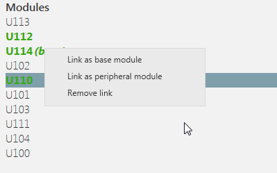
Linked modules are visualized green and unlinked modules yellow if the Link mode is active.
The controller will be named according to its base e.g Base name U114 gives a controller named 1140A1.
Note that the list of modules will be sorted by the distance from the selected Controls device.
Modules already linked to another controller will be marked as linked in the Modules list.
Step 4 Edit IO Mapping - Optional
When using the Link functionality the IO assignment is done automatically. If, for any reason, the IO mapping is desired to be changed this can be done by using the Edit IO mapping functionality.
Tip! By using the Reset the Edit IO Mapping drop down all manual changes are removed for the selected controller.
Click Controls tab -> Distributed Controller group -> Edit IO Mapping and a Edit IO Mapping panel is shown on right hand side.

All connector on the distributed controller are available for edit and are marked as DI (Input) DO (Output) or IO (Configurable as Input or Output). Each Connector has a drop-down menu populated with available connection options.
Tip! There is an option to show only unmapped signals.
Step 5 Export IO Mapping - Optional
Click Controls tab -> Distributed Controller group -> Export IO Mapping and a pop up menu will appear.
It will export a zip file containing the total IO mapping as a csv file and one file per controller.