Since chains, slide rails and rivets are cumbersome to draw and incorporate in a drawing with the correct amount and length, there is an automated way of calculating the chain, slide rail and rivets needed in FlexCAD AutoCAD. And of course is the Part list populated correctly.
This function also help the user to make the correct choices. Mainly a chain fits to a specific conveyor platform type, but sometimes a chain fits different platforms. With slide rail and rivets it is even trickier to know what slide rail or rivet that fits to a specific platform. The Calculate Chain function only shows the chains, slide rails and rivets allowed for the platform in question.
Before using the function you must have a conveyor (more correctly, a partly finished conveyor containing at least one idler end unit or drive unit) in the drawing.
The function can only calculate one conveyor at a time, if there are many conveyors in the drawing each conveyor needs to be calculated separately.
The Calculate Chain function is started by clicking the icon shown in the picture below.
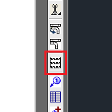
First the function asks for what components to where chain should be calculated. Again, only choose components from one conveyor, as the function only calculates one conveyor at a time. After choosing the components of the conveyor to calculated, the program asks for a starting point from where the calculation should start. Click near the idler end unit or near the drive unit. Now the window below opens.
In this window all choices of chain, slide rail and rivet are made. Typical work progress is to first choose chain, which is done in the top part of the window, but you can make choices in any order.
Choosing chain
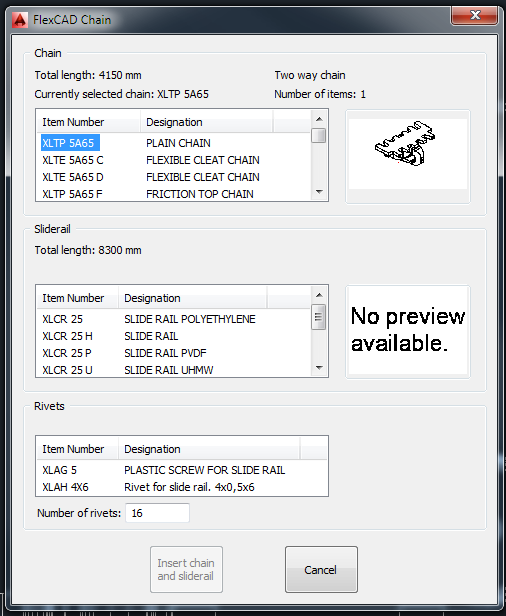
When the window is opened, the chain at the top of the list is pre-set by the program (Item Number being high-lighted), different chain is chosen by clicking on the Item Number which is then highlighted. The Designation tells what kind of chain it is, and in the small window to the right of the list there is a thumbnail image showing what the chain looks like. Above the selection window, there are four information texts
- Total length which is the total length of chain needed in the conveyor (in mm if running in ISO, in inch if running in ANSI)
- Currently selected chain which shows what chain is chosen
- Two way chain / One way chain which tells whether the conveyor has return chain (Two way chain) or top chain only (One way chain)
- Number of items which is the ordering quantity needed of chain needed (Chains are supplied by FlexLink in packages of 1, 3 or 5 m)
Choosing slide rail
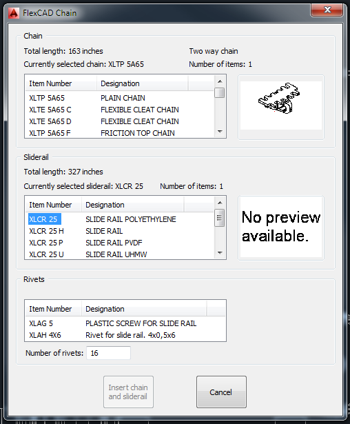
The slide rail is chosen in the middle section of the window and as for the chain, the slide rail is chosen by clicking on the Item Number which will be highlighted. As for the chain, there are some information texts above the selection window, where
- Total length which is the total length of slide rail needed in the conveyor (in mm if running in ISO, in inch if running in ANSI)
- Currently selected slide rail which shows what slide rail is chosen
- Number of items which is the ordering quantity needed of slide rail needed (Slide rails are supplied by FlexLink in lengths of 3 or 25 m)
Choosing rivets
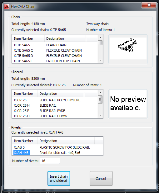
The rivets are chosen in the lowest section of the window and as for chain and slide rail, the choice is made by clicking on the Item Number. The program calculates the needed number of rivets based on the configuration of the conveyor (number of bends, length of beams etc.) and displays this number below the selection window. This is a free text window, so the number can be manually changed if the user finds the calculated number not correct.
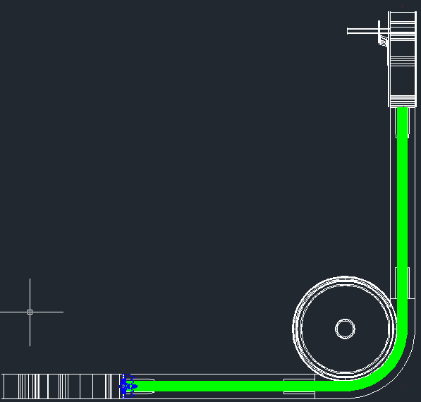
When all choices are done, the button Insert chain and slide rail is activated. When clicked, the window closes and a green line is displayed inside the beams and bends of the conveyor in question, see picture below, and the line has an AutoCAD layer of its own called cq_flexcad_chain. This line contains all the data needed to update the Part list with all the new items with their respective quantities.
Hints and tips
There are no possibilities to change the calculation after the window has been closed, so the tip is to finalize the conveyor and then make the chain calculation. If there still is a need of making an updated calculation, the only way to make it is to erase the green line running in the middle of the conveyor and make a new calculation. If beams are changed by using the function Edit beam after a chain calculation has been done, the chain calculation does NOT follow the change, it must be removed and be recalculated.
If the line showing that a chain calculation has been done is considered being disturbing or annoying in any other way, the line can be hidden by using the Chain On/Off icon, see picture below.
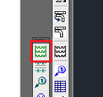
Clicking this icon will turn off the layer the line is in, making the line “invisible”. The Part list is not effected, just the drawing area.
The icon for Chain On/Off is very similar to the Calculate chain icon, green instead of black.