Background
The units in the X45e platform can be controlled in three ways. Either you have no communication with the units besides the four digital inputs. This is referred to as autonomous or stand-alone mode. If more communication is required there are two options, DeviceNet or CANopen. They are both versions of the CAN protocol. This article focuses on how to work with the DeviceNet alternative.
In the following case we have a Rockwell PLC (CompactLogix) with a DeviceNet scanner (SDN 1769).
For deeper information please check the following manuals:
User documentation – Electrical System (X45e)
User documentation – Parameter Setting Tool
Manual for Rockwell PLC and DeviceNet scanner
Prerequisites
Hardware
PC (Windows 7 or later)
Rockwell PLC (CompactLogix)
DeviceNet scanner (SDN 1769)
X45e units (with power cables)
Parameter Setting Tool cable (X45e)
CAN cables (resistor, cable with open end, daisy chain cable, bus termination)
Software
Studio 5000 or RSLogix 5000
RSNetworx for DeviceNet
X45e – Parameter Setting Tool
DeviceNet EDS files for X45e units
Standard PLC blocks for X45e communication
X45e
Make sure the nodes are supplied with power properly.
Connect a PC via the Kvaser cable to the B-Bus connector on the node.
Launch the Parameter Setting Tool and set the Network > X45e > B-Bus (CANopen)
Chose Network > Scan network F12 to see the nodes on the network
Use the command Change node set the correct setting for each node
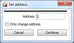
The first thing to set is the node address.
Then the type is chosen as the next step in the wizard.

Next window is for setting all network parameters

A-Bus protocol has to be set to DeviceNet – 250 kbit/s.
Enable –Reset is set to Line control. This means the X45e unit is waiting for these two command bits for enable and reset.

- Variant and Interlock can be set to appropriate values. See User documentation for details.
Physical network
Make sure the DeviceNet scanner module is mounted correct including a termination resistor.
The first CAN cable should be open in one end. Connect all five parts to the scanner module according to the picture below. The two parts for the 24VDC power should be supplied separately.

Continue to link all motor using daisy chain.
The last motor should have an M12 CAN bus termination in the end.
Network configuration (RSNetworx)
Import the EDS files for the X45e units to the component library
Build up your network with correct node addresses.
Edit the I/O parameter for each X45e unit, Input size: 5 Bytes, Output size: 2 Bytes. It is recommended to use the Change of State mode and 2000 ms as Heartbeat Rate. This means all data from the PLC will be sent as soon as the data changes and at least every 2 seconds. If the X45e unit isn't receiving the Enable bit for at least 2,5 seconds it will be stopped.

Map every node to a specific Data area.

PLC
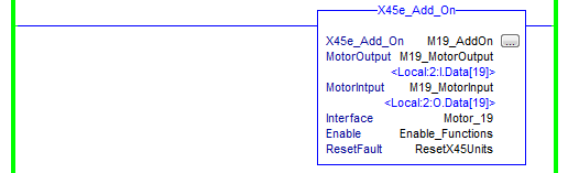
This chapter could be solved without using the X45e AddOn.
Copy the AddOn instruction for X45e
Create one X45e_Add_On for each X45e unit.
Copy the User Defined datatype X45e_Interface
Create one X45e_Interface for each X45e unit
Connect the Output and Input memory area to DataArea used by the scanner. It is recommended to use the Alias for better naming.
The interface contains a lot of both input and output bits.
The Enable and ResetFault bit are separated because they could easily be connected to a global variable.