This article shows how a layout can be exported into various other tools. The tool has been streamlined so it can be used with other FlexLink tools in a simple process to keep the manual labor to a minimum. Exporting the layout can either export a Bill of material that can be read by the Online Store, Quotation Tool, Chain Calculation Tool or Excel; or it can export the 3D or 2D model in a format that can be opened in other tools, such as Acrobat reader or Autodesk DWG Trueview.
Exporting the Bill of Material
There are two ways of exporting the Bill of material, either the Home / Send to menu group can be used to send the layout to other FlexLink tools; or the File / Export / Create Bill of material file can be used to export to a file.
Sending to Quotation Tool
In the Home / Send to to menu group, the whole bill of material can be sent to the Quotation Tool with one click, using the Home / Send to / Quotation tool button. In order to do this, the Quotation Tool needs to be started. For more information about the Quotation Tool see the Export and Import page.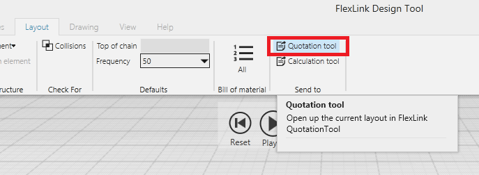
Exporting to file
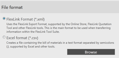
The Bill of material can also be exported to a file and stored in project folder among other related files. The file can be saved into a FlexLink format which is supported by other FlexLink tools, or in a CSV file that can be read by Excel. Most of the time, the file should be exported in the FlexLink format as it contains much more information about the layout than the common CSV file, such as configuration of drive units, etc.
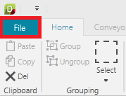
- Click on File / Export / Create Bill of Material file in the menu.
- Select the type of format the file should be
- Click Browse to select where the file should be stored.


Import of exported files into FlexLink Online Store is described in the article http://kb.flexlink.com/help/article/link/ooimport
Exporting the Model
Sending to Chain Calculation Tool
In the Layout / Send To menu group, the modeled conveyors can be sent to the Chain Calculation Tool with one click. Click on the Calculation Tool in the Layout / Send To menu group to start the tool with current layout. When the file is opened in the Calculation Tool it can be modified but changes in the tool will not be synchronized back to the Design Tool. Also, it is advised that the file is saved in another folder as the file will be replaced the next time the Design Tool sends the layout to the Calculation Tool.
3D PDF
The Design Tool can export the layout into a 3D PDF that can be opened by all modern Acrobat PDF Readers. This allows other users to view the layout in an interactive 3D view, without having any special CAD tool. A 3D PDF will also record a simulation where products can move around in the world. If simulation is not required in the PDF then the recording can be stopped immediately after it was started. This will give a static 3D world which the reader can interact with without any simulation.
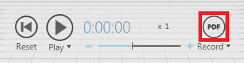
- To start recording a 3D PDF, click on the PDF icon in the simulation view. If the simulation is not started, then it will be started.
- Select where the PDF should be saved to in the File explorer that was opened.
- Now the simulation will continue and record everything that will happen in the simulation. Note that the size of the PDF file will increase as the longer the simulation is running.
- To finish recording click on the red PDF button, then the Design Tool will save the file and open the file in the default PDF reader.
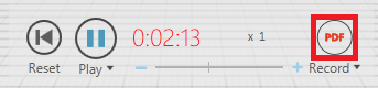


The simulation speed should be set to 1, during simulation otherwise products may jump between conveyors. The recording can be started at any time during a simulation to show a particular event in the simulation.
2D Drawing
If there is a drawing created in the Drawing tab, then it can be exported as a 2D drawing. The 2D drawing can be exported as a DXF, DWG or DXB file. See the Drawing tutorial for a more detailed guide.
- To start a drawing, click on the Drawing tab.
- Click on the Drawing Template / Add to set properties on the template, such as ANSI or ISO project, scale or paper format.
- To add the part list to the drawing, click on the Part List / Add Components to add a component part list.
- Add one or several view ports click on Viewport / Add, which shows the 3D view. Using the mouse specify the region which will be seen in the view port.
- Add dimensions or balloons to finish the drawing
- When the drawing is complete, click on File / Export / Create Drawing to show the drawing export options
- Select the 2D Drawing to export only the drawing
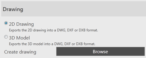
- Click Browse to select where the file should be stored.

3D Model
The layout can be exported as a 3D model which can be imported into other CAD tools, all components will be 3D models. Design Tool can export the 3D model to several file formats. For the list of all formats see the User documentation.
- Click on File / Export / Create Drawing file in the menu.
- Select the 3D Drawing to export the 3D model
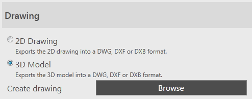
- Click Browse to select where the file should be stored.
- The file can then be imported to other cad tools such as the Autodesk DWG Trueview, which is a freeware application to read DWG files.
