Exporting the part list (or Bill of material) from FlexCAD AutoCAD is supported in two formats, .xls (Excel) and .cvs (Comma Separated Value). The .cvs files are designed to work with Online Store (FlexLink’s web shop) and FlexLink Quotation Tool (FLQT), whereas the .xls format is a service to those who wish to use Excel for calculating their quotes.
The export function do not work unless the drawing is saved, the files derived from the function are saved with the same name and in the same folder as the drawing.
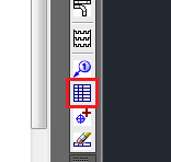
The part list is started by clicking on the Part list icon, see picture below.
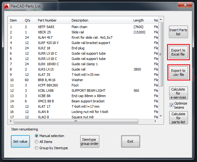
First choose which parts should be in the part list, default value shown in the command line is ALL, which selects all parts in the drawing and the following window opens. The two export buttons are found at the right hand side of this window.
Clicking any of the export buttons will result in a new file and it is notified in the program as below:
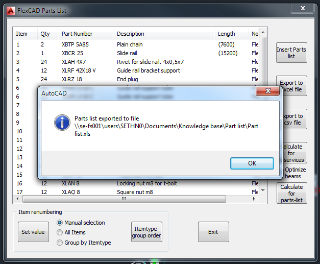
Clicking OK just closes the information window, the Part list window will remain open.
What is in the export file?
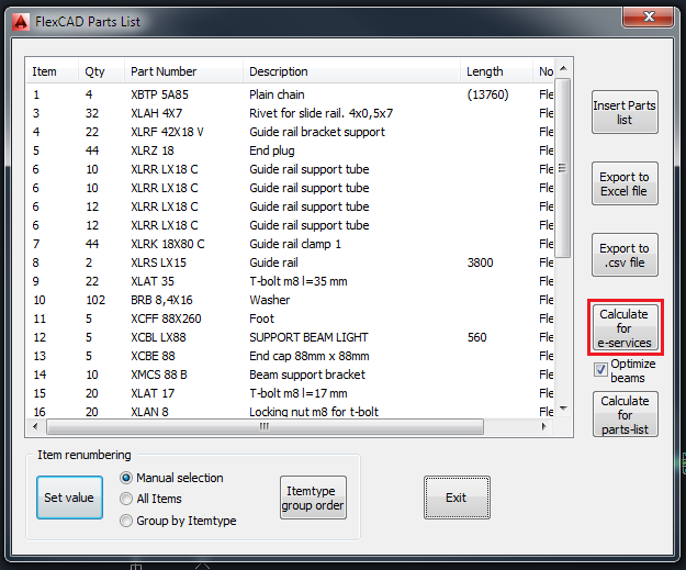
The content in the export file can to some extent be manipulated in the Part list function before being exported. This manipulation is done by clicking the Calculate for e-services button, see picture below. Clicking this button recalculates the chain and slide rails to the correct ordering quantity. To explain further, if there are more than one conveyor in the drawing, before clicking Calculate for e-services the quantity of chain and guide rail will show the sum of the chain calculations made with the correct chain and slide rail lengths shown within brackets. After clicking Calculate for e-services the quantity is correct and the lengths within brackets are gone. Also all guide rails are recalculated to 3 meter lengths, since guide rails cannot be ordered in cut-lengths.
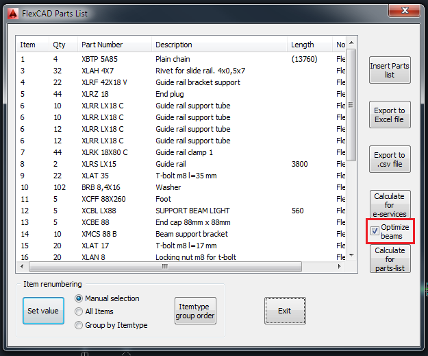
If it desired that also conveyor beams and support beams should be recalculated to 3 meter lengths, the check box Optimize beams should be checked, as in the picture below. If checked, all beams are recalculated to 3 meter lengths and a new text file called “drawing name BeamCut.txt” is created and placed next to the drawing in the folder structure. In this file it is explained how the 3 meter beams should be cut to produce the beams in the drawing.
